CBM1088 JIS Angle Stop-Check Valve
manufacturer: Kaiweixi Valve Group Co., LTD.
E-mail: Yannie@kaiweixi.com
Tel: +86(577)67038872
Mob: +86 189 6779 6135(WeChat Same Account)
product drawing
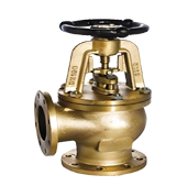
CBM1088 JIS Angle Stop-Check Valve
Overview
The CBM1088 JIS Angle Stop-Check Valve is a specially designed combination valve compliant with Japanese Industrial Standards (JIS), featuring an angled flow path configuration. The valve body is typically constructed from cast steel or stainless steel, with the inlet and outlet arranged at a 90-degree angle. This valve integrates dual functions: manual shut-off control and automatic check backflow prevention.Through handwheel rotation, the valve disc is actuated to achieve flow shut-off control, while the built-in check mechanism automatically prevents reverse flow when the valve is in the open position. Designed in strict accordance with JIS standards, this valve is specifically intended for marine piping systems, Japanese industrial equipment, and specialized pipeline layouts requiring right-angle flow direction changes. It provides comprehensive functionality—including flow redirection, flow shut-off, and backflow protection—within confined spatial constraints.
Features
1. 90° Flow Path with Dual-Function Integration
The 90° angled design eliminates the need for additional pipe elbows, simplifying pipeline layout. It integrates manual shut-off and automatic check functions into a single valve, enabling multi-functional control within compact spaces.
2. Strict Compliance with JIS Standards
The design and manufacturing fully comply with JIS B2003 and related standards, ensuring compatibility with Japanese-standard marine and industrial systems in terms of pressure ratings, connection dimensions, and material requirements.
3.Dual Sealing for Reliable Control
The shut-off section features a metal-sealed spiral lifting mechanism, providing smooth operation and reliable sealing. The check section responds automatically to flow direction, ensuring quick and tight closure.
4. Space-Saving Optimized Layout
The angled design reduces the need for pipe turning fittings, while the integrated functionality avoids the installation of multiple valves, significantly optimizing equipment space utilization and pipeline complexity.
5. Marine-Oriented Ease of Maintenance
Designed specifically for confined environments such as ship engine rooms, this valve is structurally robust and vibration-resistant. The shut-off disc and check disc can be inspected and serviced separately, meeting marine equipment maintenance requirements.
Dimensions & constructral diagram

CBM1088 JIS Angle Stop-Check Valve constructral diagram
Material of main parts
| NO. | Name | Material |
|---|---|---|
| 1 | Body | Cast Iron, Cast Steel, Copper |
| 2 | Disc | Cast Iron, Cast Steel, Copper |
| 3 | Stem | Cast Iron, Cast Steel, Copper |
Performance Specification
| Performance Specification | ||
|---|---|---|
| Nominal Pressure | 1.6/1.0/2.5 | MPa |
| Shell Test Pressure | 2.4/1.5/3.75 | |
| Seal Test Pressure | 1.76/1.1/2.75 | |
| Suitable Temperature | ≤80 | ℃ |
Specification and dimensions
| DN | Size | L | D | D1 | D2 | f | b | z-Φd | Do | H1 | HE | V |
|---|---|---|---|---|---|---|---|---|---|---|---|---|
| 15 | 1/2 | 65/90 | 95 | 65 | 45 | 2 | 16 | 4-Φ14 | 100 | 240 | 270 | 7.5 |
| 20 | 3/4 | 75/95 | 105 | 75 | 55 | 2 | 16 | 4-Φ14 | 100 | 240 | 270 | 7.5 |
| 25 | 1 | 90/100 | 115 | 85 | 65 | 2 | 16 | 4-Φ14 | 140 | 280 | 335 | 13 |
| 32 | 1 1/4 | 105/115 | 135 | 100 | 78 | 2 | 18 | 4-Φ18 | 140 | 280 | 335 | 13 |
| 40 | 1 1/2 | 115/125 | 145 | 110 | 85 | 3 | 18 | 4-Φ18 | 160 | 320 | 400 | 25 |
| 50 | 2 | 135/160 | 160 | 125 | 100 | 3 | 20 | 4-Φ18 | 160 | 320 | 400 | 25 |
| 65 | 2 1/2 | 160/190 | 180 | 145 | 120 | 3 | 20 | 4-Φ18 | 200 | 400 | 450 | 31 |
| 80 | 3 | 180/210 | 195 | 160 | 135 | 3 | 22 | 8-Φ18 | 200 | 400 | 450 | 31 |
| 100 | 4 | 230/255 | 230 | 190 | 160 | 3 | 24 | 8-Φ23 | 260 | 500 | 565 | 50 |
| 125 | 5 | 300 | 270 | 220 | 188 | 3 | 24 | 8-Φ25 | 300 | 600 | 675 | 65 |
| 150 | 6 | 350 | 300 | 250 | 218 | 3 | 24 | 8-Φ25 | 300 | 600 | 675 | 65 |